









Updated 2 months ago
Garden Tool Failure Points: Why Heads Loosen, Handles Split, Tines Bend, and Coatings Peel
SCARECROW GARDEN SUPPLIER

Garden Tool Failure Points: Why Heads Loosen, Handles Split, Tines Bend | Scarecrow Garden Supplier
Key Takeaways
- Tool failure is rarely caused by a single material problem. Most failures result from a combination of design, manufacturing, use, and transport factors that need to be investigated — not assumed.
- Loose heads, split handles, bent tines, and peeling coatings each have distinct possible causes. Identifying the right cause requires evidence: photos, batch information, use conditions, and sometimes fracture surface analysis.
- A “possible cause” is not a “confirmed cause.” Jumping to conclusions from a single photo leads to wrong specifications and wasted corrective actions.
- The most valuable thing a buyer can do with after-sales complaints is feed them back into specifications and QC checklists — turning problems into prevention.
- Transport damage is a real failure category that is often misattributed to manufacturing. Always check whether the damage occurred in transit before blaming the factory.
A customer returns a rake with a loose head. Another sends a photo of a shovel handle split down the middle. A third reports fork tines bent after one use. Your first instinct is to contact the factory and complain about quality. But which quality problem? Was it the material? The manufacturing? The design? The packaging? Or was it the way the tool was used?
This guide walks through the most common failure points across rakes, shovels, and garden forks — what causes them, what evidence to collect, and how to turn after-sales problems into better specifications. The goal is not to assign blame. It is to identify the right corrective action.
Who this guide is for: Buyers, QC teams, retailers, and after-sales teams who deal with tool failures and need a structured approach to diagnosis and prevention.
Failure Is Not a Single Material Problem
When a tool fails, the instinct is to blame the steel. But a garden tool is a system: head, socket, fastener, handle, grip, coating, and packaging. Each component interacts with the others. A forged head with excellent steel can still fail if the socket is too short, the rivet is undersized, or the handle was kiln-dried too aggressively.
The same failure mode — say, a loose head — can have completely different root causes:
- A rivet that was too small for the socket diameter
- A wooden handle that swelled and shrank with moisture changes, working the rivet loose
- Impact during transit that deformed the socket before the tool was ever used
- A socket depth that was specified too short from the beginning
Each cause requires a different fix. Specifying “use bigger rivets” does not solve a moisture-related problem. Specifying “longer sockets” does not solve a transit damage problem. This is why investigation matters.
Preventing these failures requires repeatable testing methods. See Garden Tool Testing for Buyers: Load, Bending, Impact, Coating, Corrosion, and Packaging Tests.
Loose Heads: Socket, Fastener, Moisture, Impact, and Packaging
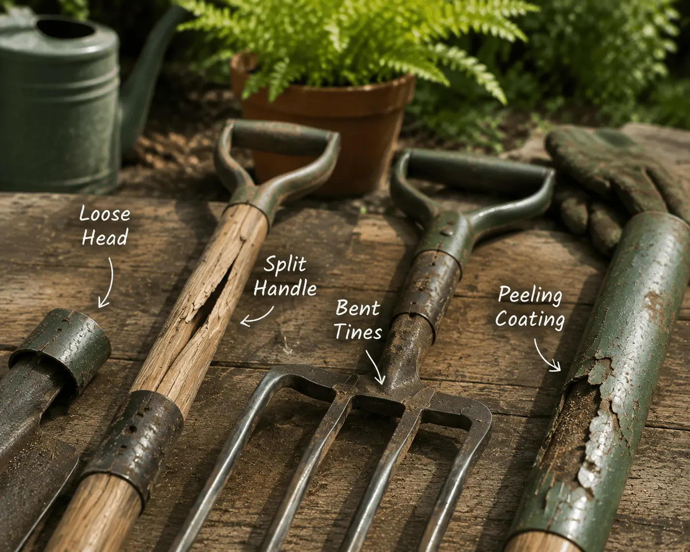
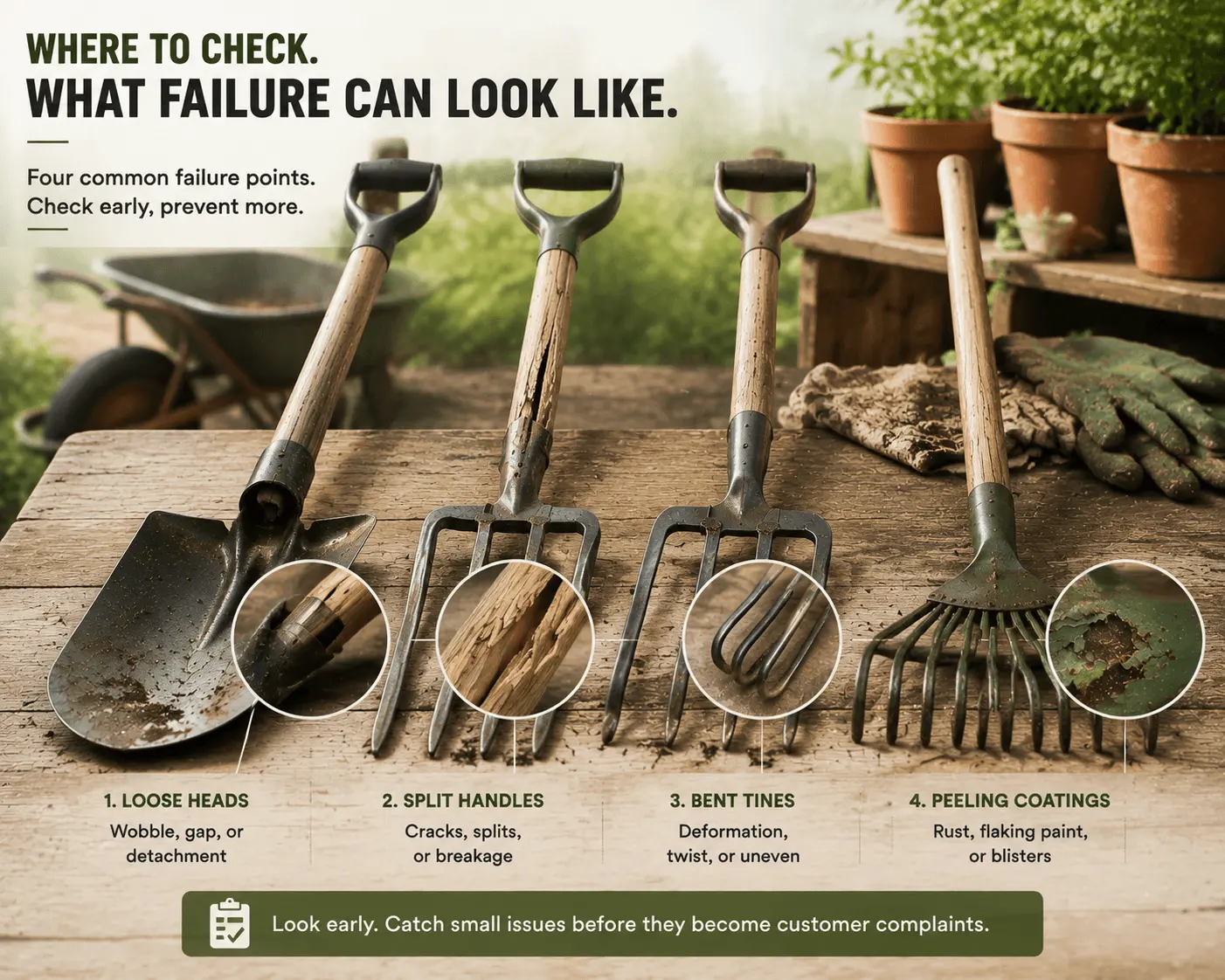
Symptoms
- Head wobbles on the handle during use
- Rivet or bolt visible above the socket — not flush
- Gap between handle top and socket interior
- Head detaches completely during use
Possible Causes
| Cause Category | What Happens | How to Investigate |
| Socket fit | Socket diameter too large for handle; or socket too short for adequate engagement | Measure socket depth and internal diameter; compare to handle dimensions |
| Fastener | Rivet undersized; bolt loose; rivet not properly compressed | Check fastener diameter, material, and compression; compare to specification |
| Moisture (wood handles) | Wood swells in humid conditions and shrinks in dry conditions, working the fastener loose over time | Check handle moisture content; ask about storage conditions; look for seasonal patterns in complaints |
| Impact (transit) | Tool dropped or compressed during shipping, deforming the socket before use | Check packaging; inspect for impact marks on carton; compare to ISTA transit test results |
| Adhesive failure | If adhesive was used in addition to mechanical fasteners, it may have degraded | Check for adhesive residue; confirm whether adhesive was specified |
Prevention
- Specify socket depth minimum (typically 50 mm for mid-range; 65 mm for professional)
- Confirm fastener diameter and type match the specification
- For wood handles: confirm moisture content target (typically 12–15% at time of assembly)
- Review packaging to prevent head-to-head contact and handle compression
- For professional markets: use through-bolts that can be re-tightened or replaced
The USDA Forest Products Laboratory’s Wood Handbook documents how wood absorbs and releases moisture depending on ambient humidity — this is not a defect, it is a material property. Understanding it helps specify the right handle treatment and storage guidance.
Split Handles: Wood Grain, Knots, Hole Position, Overload, and Transit
Symptoms
- Handle splits along the grain — typically starting from the top (socket end) or from a pre-drilled hole
- Crack runs lengthwise along the handle
- Fiberglass handle shows delamination or surface cracking
Possible Causes — Wood Handles
| Cause Category | What Happens | How to Investigate |
| Grain orientation | Grain runs at an angle to the handle axis, creating a weak plane | Inspect grain direction on the split surface; compare to handle specification |
| Knots | A knot or knot hole creates a stress concentration | Look for knots near the split origin; check handle grading standard |
| Hole position | Pre-drilled hole for rivet/bolt is too close to the handle edge, reducing cross-section | Measure distance from hole center to nearest edge; compare to specification |
| Overload | Tool used as a lever beyond its design intent (e.g., prying with a shovel) | Ask about use conditions; check for bending in addition to splitting |
| Moisture | Handle dried too much after assembly, creating internal stress | Check moisture content; look for seasonal patterns |
| Transit | Handle bent or impacted during shipping, initiating a crack | Check packaging; look for impact marks on carton |
Possible Causes — Fiberglass Handles
| Cause Category | What Happens | How to Investigate |
| Surface damage | Outer layer scratched or impacted, exposing fibers to moisture and stress | Look for impact marks near the crack origin; check if outer layer is intact elsewhere |
| Overload | Fiberglass can fail under extreme bending or impact loads | Ask about use conditions; check for fiber fracture pattern |
| Connection stress | Stress concentrated at the handle-to-socket junction | Inspect the area where the handle enters the socket for cracking |
Prevention
- For wood handles: specify grain orientation (straight grain preferred), knot limits, and hole position tolerances
- Confirm handle moisture content at assembly
- For fiberglass: specify outer layer integrity requirements and inspect for surface damage on arrival
- Provide accurate use instructions — “this shovel is for moving loose material, not for prying embedded objects”
- Review packaging to prevent handle bending and impact during transit
Handle failures are closely related to material selection and construction. Learn more in Wood vs. Fiberglass Handles Across Rakes, Shovels, and Forks: Cost, Durability, Repairability, and Branding.
Bent Tines and Broken Tines: Cross-Section, Material, Heat Treatment, Tine Root, and Use
Symptoms
- Tine bent out of alignment with adjacent tines
- Tine permanently deformed after normal use
- Tine snapped at the base or mid-section
- Bent tine does not return to original position
Possible Causes
| Cause Category | What Happens | How to Investigate |
| Cross-section | Tine cross-section too small for the load; or section shape does not provide adequate bending resistance in the load direction | Measure tine cross-section (two dimensions); compare to specification; check if section is consistent across all tines |
| Material | Steel not heat-treated; or heat treatment incorrect (too soft = bends; too hard = snaps) | Confirm whether heat treatment was specified; if possible, arrange hardness testing |
| Tine root geometry | Sharp transition at the base of the tine creates a stress concentration | Inspect the tine-to-head transition; look for sharp corners vs. radiused transitions |
| Use mismatch | Tool used for a task it was not designed for (e.g., a leaf rake used to move gravel) | Ask about use conditions; check if multiple tines are bent (suggests overload) vs. single tine (suggests impact) |
| Manufacturing defect | Tine not properly aligned during welding or forging; or material defect | Check tine alignment across the batch; look for consistent vs. random failure patterns |
Bent vs. Broken: What It Tells You
A bent tine and a broken tine point to different problems:
- Bent tine (permanent deformation, no fracture): The tine yielded under load. This typically means the material is too soft for the application — either the steel grade is insufficient, or heat treatment was not applied or was inadequate. The tine absorbed energy by deforming rather than fracturing.
- Broken tine (fracture, no deformation): The tine snapped without significant bending. This typically means the material is too hard or brittle — heat treatment may have been too aggressive, or the tine root has a stress concentration (sharp corner) that initiated a crack.
- Bent then broken: The tine bent first, then fractured at the bend. This can indicate fatigue — repeated loading that eventually exceeded the material’s capacity.
The Forging Industry Association notes that forging refines the steel’s grain structure, which can improve performance at stress concentration points like tine roots. But forging alone does not guarantee adequate performance — the geometry, heat treatment, and use conditions all contribute.
Blade Deformation: Thickness, Geometry, Load Position, and Socket
Symptoms (Shovels and Spades)
- Blade bent backward at the shoulder (where blade meets socket)
- Blade warped or dished — not flat
- Cutting edge deformed or rolled
- Blade cracked at the shoulder
Possible Causes
| Cause Category | What Happens | How to Investigate |
| Thickness | Steel too thin at the shoulder for the applied load | Measure thickness at the shoulder; compare to specification; check if thickness is uniform or thinned at formed areas |
| Geometry | Blade shape or curvature does not provide adequate stiffness | Compare blade profile to specification; check if shoulder has reinforcement |
| Load position | Force applied at the blade tip (maximum leverage) rather than at the shoulder | Ask about use conditions; check foot step position |
| Socket | Socket too short to distribute force into the handle | Measure socket depth; check for deformation at the socket-to-blade transition |
| Material | Steel not heat-treated; or forming process thinned the shoulder | Confirm material and forming method; measure thickness at multiple points |
Prevention
- Specify actual steel thickness in mm at the shoulder (not just the raw sheet gauge) — and measure post-forming, since stamping can thin the shoulder
- Confirm blade geometry includes shoulder reinforcement where needed — a deeper dish or reinforced shoulder distributes load more effectively
- Specify foot step design that distributes force across the blade rather than concentrating it at the shoulder
- For professional tools: specify forged construction, which maintains more uniform thickness distribution than stamping
- Review whether the tool is being used for its intended task — a square point shovel for moving loose material should not be used as a pry bar for embedded objects
Coating Peeling and Rust: Pre-Treatment, Edge Coverage, Adhesion, Damage, and Storage
Symptoms
- Paint or powder coating flakes off in sheets or chips
- Rust appears at cut edges, tine tips, or blade edges
- Coating bubbles or blisters
- Rust appears under intact-looking coating (undermining)
Possible Causes
| Cause Category | What Happens | How to Investigate |
| Surface preparation | Steel surface not properly cleaned (oil, rust, scale) before coating | Inspect the coating underside for contamination; check if coating adheres to bare steel or separates cleanly |
| Edge coverage | Cut edges (tine tips, blade edges, stamped edges) not coated — bare steel exposed | Visually inspect edges and tips; look for rust starting at edges specifically |
| Adhesion | Coating does not bond to steel surface | Perform ASTM D3359 tape adhesion test on a sample; compare to specification |
| Mechanical damage | Coating scratched or chipped during use, transit, or storage | Look for impact marks or scratches near the coating failure; check packaging |
| Storage | Tools stored damp or in humid conditions, accelerating corrosion at any exposed steel | Ask about storage conditions; check if failure correlates with specific batches or seasons |
| Coating type mismatch | Painted finish used where powder coating was needed | Confirm coating type against specification; painted finishes are thinner and less durable than powder coating |
The Edge Problem
This is the most common coating failure across all tool types. When steel is stamped or cut, the cut edges are bare metal. If the coating process does not address edges — and many do not — rust begins at the edge and works inward under the coating. This is not a coating adhesion failure; it is a coverage failure.
Professional-tier tools should address edge coverage through:
- Powder coating (which wraps edges better than liquid paint)
- Pre-treatment that includes edge cleaning
- Post-coating inspection of edges and tips
ASTM D3359 and B117: What They Tell You
ASTM D3359 (tape adhesion test) tells you whether the coating is bonded to the steel surface. It is a practical test that can be performed on samples.
ASTM B117 (salt spray) tells you how the coating performs in a standardized corrosive environment. It does not predict outdoor service life — hours of salt spray exposure do not translate to years of rust-free use. Use B117 as a comparison tool between coatings, not as a lifetime predictor.
The American Galvanizers Association documents how zinc coatings provide both barrier protection (physical separation from air and moisture) and sacrificial protection (zinc corrodes preferentially to steel). Galvanizing is one option for edge protection — but it is not standard for garden tools unless specifically specified.
How to Conduct a Failure Investigation
When a failure is reported, follow a structured investigation process:
Step 1: Collect Evidence
- Photos: Multiple angles, including the failure point, the surrounding area, and the overall tool
- Batch information: Production date, model number, PO number
- Quantity affected: Is this one tool or a pattern across a batch?
- Use conditions: What task was the tool performing? How much force? What material was it working in?
- Age: How long has the tool been in service?
- Storage: How was the tool stored before and between uses?
Step 2: Identify the Failure Mode
- Is this a manufacturing defect (affecting one tool in a batch)?
- Is this a design issue (affecting multiple tools across batches)?
- Is this a use issue (the tool was used for a task it was not designed for)?
- Is this a transit issue (damage occurred during shipping)?
Step 3: Determine Possible Causes
Use the tables above to identify possible causes. Remember: a possible cause is not a confirmed cause. Multiple causes may be contributing.
Step 4: Confirm with Evidence
- For material issues: arrange hardness testing or chemical analysis through a third-party laboratory
- For design issues: compare measurements to specification
- For transit issues: review packaging and compare to ISTA test results
- For use issues: compare the failure to the tool’s intended use
Step 5: Implement Corrective Action
- Specification change: Update the specification to prevent recurrence (e.g., longer socket, thicker steel, different fastener)
- QC checklist update: Add inspection points that would have caught the issue
- Packaging change: Modify packaging to prevent transit damage
- Use instruction: Add or clarify use guidance on packaging or labeling
Turning After-Sales Problems into Better Specifications
The most valuable output of a failure investigation is not a single fix. It is a permanent update to your specification and QC checklist. Here is how to do it:
Create a Failure-to-Specification Feedback Loop
| Failure Mode | Specification Update | QC Checklist Addition |
| Loose head | Specify minimum socket depth and fastener diameter | Add socket depth measurement and fastener check to inspection |
| Split handle | Specify grain orientation, knot limits, hole position, moisture content | Add grain inspection and moisture check to handle QC |
| Bent tine | Specify tine cross-section, heat treatment, and tine root radius | Add tine cross-section measurement and alignment check |
| Blade deformation | Specify steel thickness at shoulder (post-forming) and blade geometry | Add thickness measurement at shoulder and flatness check |
| Coating failure | Specify coating type, edge coverage requirement, and pre-treatment | Add edge coverage inspection and ASTM D3359 adhesion check |
Track Failure Patterns
- Maintain a log of after-sales complaints by model, failure type, and batch
- Look for patterns: if one model has a higher rate of loose heads, the specification for that model needs review
- Share the log with your supply team — they can use it to identify which factories or models need specification updates
Do Not Blame the Factory First
Many failures are specification issues, not manufacturing issues. If the specification did not require a minimum socket depth, the factory did not do anything wrong by making a short socket. The fix is to update the specification — not to demand that the factory “do better” without telling them what “better” means.
FAQ
How can I tell if a failure is a manufacturing defect or a use issue? Look at the pattern. If one tool in a batch fails, it may be a manufacturing defect. If multiple tools across batches fail in the same way, it is more likely a design or specification issue. If the failure shows signs of extreme overload (bent in a direction the tool was not designed for), it may be a use issue. Collect photos, batch information, and use conditions before drawing conclusions.
Can I determine the cause of a failure from a photo? A photo can identify the failure mode (bent tine, split handle, loose head) and suggest possible causes. But it cannot confirm the root cause. Material issues require hardness testing or chemical analysis. Design issues require measurement against specification. Always collect additional evidence before changing specifications.
What should I do if customers report the same failure repeatedly? Treat it as a specification issue, not a one-off complaint. Collect all available evidence (photos, batch numbers, use conditions), identify the failure mode, determine possible causes using the tables in this guide, and update the specification and QC checklist to prevent recurrence. Share the updated specification with your supply team.
Is transit damage a real failure category? Yes. Long-handled tools are particularly vulnerable to transit damage because of their length and the weight of the head. Handles can bend, heads can impact each other, and coatings can chip during shipping. Always check packaging and look for impact marks before attributing a failure to manufacturing. ISTA transit testing can help identify whether packaging is adequate.
Should I stop buying from a factory after a failure? Not necessarily. First, determine whether the failure is a manufacturing issue, a specification issue, or a use issue. If the specification was clear and the factory did not meet it, that is a manufacturing issue. If the specification was silent on the parameter that failed, that is a specification issue — the fix is to update the specification, not to change factories.